- #Arduino uno pinout reference serial
- #Arduino uno pinout reference software
- #Arduino uno pinout reference code
The on-board Erase button allows to erase the Flash Memory of the SAM3X. ADC in Arduino Due is a 6-channel converter of 10-bit. The voltage from 0 to 5 is mapped into the integer value from 0 to 1023. The ADC (Analog to Digital Converter) is used to map the voltage value to the integer value.
#Arduino uno pinout reference serial
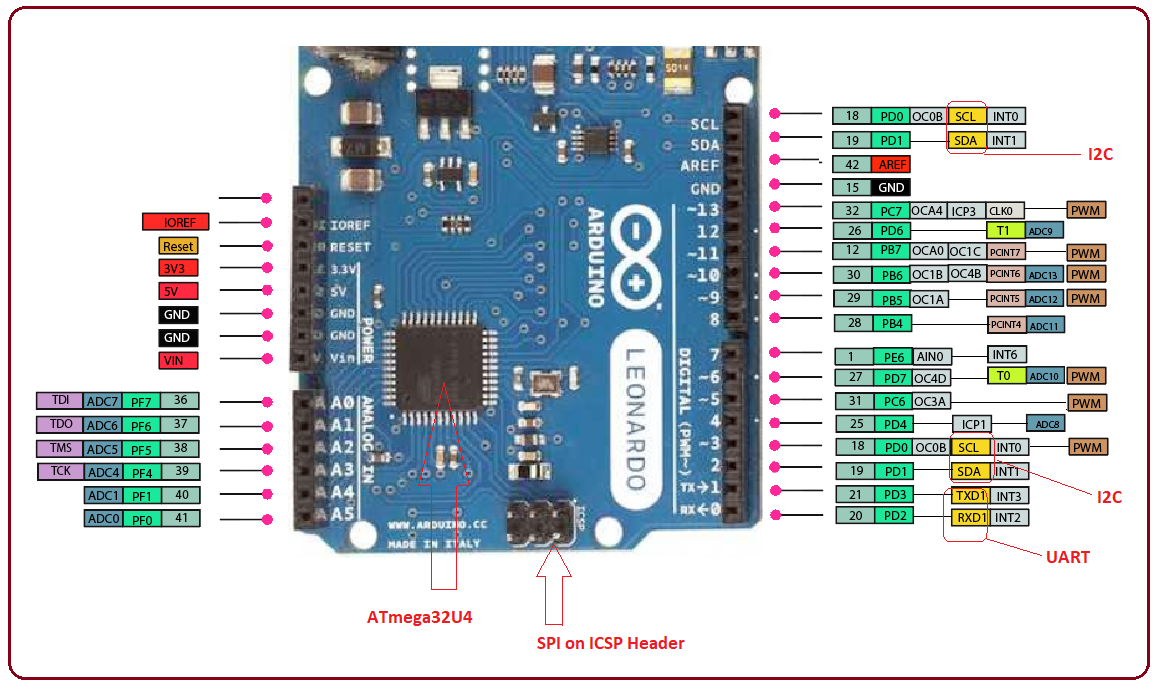
The I2C (Inter-Integrated Circuits) is a serial communication protocol that uses SCL (Serial Clock) and SDA (Serial Data) to receive and send data between two devices. It is also used to communicate between the two Microcontrollers. It can communicate quickly over short distances. It uses conductors for data receiving, data sending, synchronization, and device selection (for communication). SPI stands for Serial Peripheral Interface, which is considered as a system for serial communication. The pins labeled from 0 to 53 are the digital pins. The digital pins have the value HIGH or LOW. It can also act as GPIO (General Purpose Input Output) pins. The function of Analog pins is to read the analog sensor used in the connection. The pins numbered as Ao, A1, A2, A3, A4, A5, A6, A7, A8, A9, A10, and A11 are the analog pins. The Microcontroller operates with the reference voltage provided by the IOREF. The shields are connected to the Arduino Board. It allows the shields to check the operating voltage (3.3V or 5V) of the board. IOREF: It stands for Input-Output voltage REFerence. Vin: It is defined as the input voltage, which is applied to the Arduino Board when it is using an external power source. It can provide power to the SAM3X Microcontroller. The power can be supplied to the board from either of the above-specified sources.ģV3: The 3V3 pin works as the output regulated voltage of 3.3V. The power source of 5V for the Arduino Due board are USB connector, DC power jack, and the Vin. GND: These are the ground pins, which are used to ground our circuit.ĥV: The 5V pin works as the output regulated voltage of 5V. The power pins consist of GND (Ground), 5V, 3V3, Vin, and IOREF pins. The successful flow of data is represented by the lighting of the TX and RX LED. The pinout of Arduino Due is shown below: It has two ports, which are named as Native USB port and Programming port. It is the first Arduino board that is developed based on the ARM Microcontroller. If you are getting any trouble while working on it then ask in the comments and I will help you out.The Arduino Due is based on the 32- bit ARM core. I must add it's just the tip of the iceberg and there's a lot we can do with this Microcontroller board. So you must have got the picture of its uses. A few of its working fields are as follows: It's the most commonly used Microcontroller board.
#Arduino uno pinout reference code
If you have bigger data or code etc to save then you shouldn't select this one, I would recommend Arduino Mega. Memories are of main concern while selecting a microcontroller for your project.
#Arduino uno pinout reference software
We can also design software serial as well.

If you want to use SPI modules then you have to stick to SPI Pins and if you want to interface Serial modules like GSMm or GPS then you need to use Serial Pins. So, these digital and analog pins are capable of multiple functions and it totally depends on your project's requirement.

Arduino UNO is a Microcontroller board designed by in Italy.Let's have a look at the basic details of Arduino UNO:

So, let's cover this one from the basics: You should have a look at the Arduino UNO Pinout Diagram if you are planning to start working on this microcontroller board. You can design its libraries for different sensors etc. I really admired the idea as they have kept everything open source. Arduino UNO is the most commonly used Microcontroller board designed by in Italy. In today's tutorial, I am going to share all the basic details about Arduino UNO. Hello friends, I hope you all are doing great.


 0 kommentar(er)
